Bandpass Filters (CATV and OFF-Air-Antenna)
| CF7W, CF7W HR | Wide Non-Adjacent Bandpass Filters for Off-the-Air TV and LTE 700 MHz bands (5 to 900 MHz) |
| CF7W-VHF, UHF | Wide Bandpass filters for Off-the Air VHF, VHF-UHF, UHF |
| CFAL |
Single Channel Adjacent Bandpass Filter (CATV: T7 to T13, IF, 2 to 25) |
| BP7 | Single Channel Adjacent Bandpass (CATV: 14 to 85) |
| VF7-UHF | Frequency Tunable UHF Single Channel Bandpass |
| VF7-ch.7-13 | Frequency Tunable Single Channel VHF Bandpass |
| CF7 |
Single Channel Semi-Adjacent Bandpass Filter (CATV, VHF and UHF) |
| BP7-UHC | UHF/Hyperband Bandpass Filter for UHF Chs 14-69, CATV chs 62-125, LTE 700 MHz block (A,B or C) |
| NF7 and VF7 | Narrow 0.5 MHz and 2 MHz Bandpass Filter (5- 450 MHz) |
| BP7-CEW | Multiple Channel Adjacent Bandpass Filter (5- 600 MHz) |
Adjacent Channel Bandpass (any channel from 5 to 250 MHz)
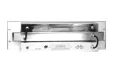
CFAL and CFAS
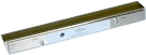 CFAL:
CFAL:Dim 1.75"H x 19"L x 3"D
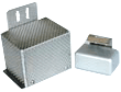
CFAS:
Dim: 4.25"L x 2.5"W x 3.25"H
Model CFAL and CFAS are designed to pass one specific TV channel, reject the adjacent channels, and all out-of -band frequencies. Channels available (CATV): T7 - T13, 2 - 13, A5 - A1, A14 - I22, 23 - 30, and TV-IF (41 to 47 MHz). Available for NTSC and ATSC system.
- Operating Bandwidth: 5 to 750 MHz
- Passband loss: < 3.5 dB (4 to 5dB at band edges)
- Return Loss:15 dB typical (except band edges)
- CFAL- rejection: >30 dB on adjacent carrier, > 20 dB on rest of channel, > 35 dB out-of-band
- CFAS (outdoor version of CFAL) - rejection: > 25 dB on adjacent carrier, and >15 dB on rest of channel, > 30 dB out-of -band
- Custom passband: any frequency band (2 to 16 MHz wide) within 5 to 250 MHz (e.g., CFAL-ch.14 -16)
- Both models are also available in 50 ohms (BNC)

Example Graphs
CFAL-chs 8, T10, CFAL-ch.14 -16
Adjacent Channel Bandpass (any channel 170 to 560 MHz)
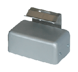
BP7-Series: BP7-HT and BP7-CE (custom)

BP7-HT: Wall mount
Dim 6 "H x 9.25 "L x 4.5 "W
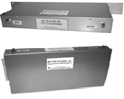
 BP7-CE:
 Dim: 3.5-5"H x 19 "L x 6 "D
High performance bandpass filters are designed for CATV operation. BP7-HT provides single channel passband and adjacent channel rejection. Use to filter modulators for adjacent operation (ex: chs 53, 54, 55). Available for NTSC and ATSC channels.
- Channels available BP7-HT: 7 to 13, 23 to 65
- Passband loss: 3 to 5 dB ( 5 to 6.5dB band edge)
- BP7-HT- rejection: >25 dB on adjacent carrier, >20 dB on rest of channel, > 40 dB out-of -band
- Operating Bandwidth: 5 to 750 / 1000 MHz
- BP7-CE - Custom channel/rejection bandpass
- Custom passband: any frequency band (4 to 8 MHz wide) within 120 to 560 MHz
- Rack and wall mount models available
- Supplied with final production graph

Example Graphs
Tunable UHF Bandpass
VF7-UHC HT General purpose, tunable, UHF 6 MHz bandpass 470 - 620 MHz
VF7-UHF: Wall mount
Dim 4.5 "H x 3.5 "L x 1.75 "W
UHF Channel Tunable bandpass filter designed for Off air antenna systems. It is suitable as pre-selector for 6 MHz TV/RF signal that requires low thru loss and does not require high signal selectivity. Tunable frequency range: 470 to 620 MHz (option ex: 550-700 MHz, 650- 800 MHz, 750-900 MHz).
 VF7-UHC HT info sheet and sample graphs
- Two screw tuners for frequency adjustment (RF instrument to view passband frequency response while tuning is required)
- Passband loss: 1.5 to 1.0 dB (470 to 620 MHz)
- Out-of band rejection @470 MHz: >20 dB 14 MHz from band edges
- Out-of band rejection @620 MHz: >20 dB 24 MHz from band edges
- Operating Bandwidth : 5 to 1300 MHz
- Connectors: type F female 75 ohms
- Options 50 ohms connectors available - inquire
- Wall mount (option: Rack mount on 1.75 x 19" panel)
- Supplied with final production graphs
Tunable UHF Bandpass (Range 450-540 MHz; 530-620 MHz)
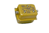
VF7-UHF: VF7-470/540; VF7-540/600
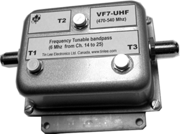
VF7-UHF: Wall mount
Dim 4.0 "H x 1.75 "L x 2 "W
UHF Channel Tunable bandpass filter designed for Off air antenna systems. Also suitable as pre-selector for 6 to 8 MHz RF sisnals. Two models are available to cover frequency ranges: 450 to 540 MHz, 530 MHz to 620 MHz. Provides single channel passband and good out of band rejection.
VF7-UHF data sheets and sample graphs
- Accessible screw tuners for frequency adjustment (RF instrument to view passband frequency response while tuning is required)
- Passband loss: 2.5 to 3.25 dB
- Out-of band rejection: >10 dB @6 MHz from band edge >20 dB @10 MHz from band edge of channel, >40 dB approx 30 MHz from bandedge
- Operating Bandwidth: 5 to 1000 MHz
- Connectors: type F female 75 ohms
- Options 50 ohms connectors available - inquire
- Wall mount and Supplied with final production graph
Tunable VHF-Hi Bandpass (Range 174-216 MHz)
VF7-ch.7-13 (174-216 MHz)
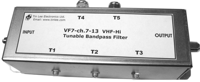
VF7-ch.7-13: Wall mount
Dim: 2.0 "H x 7.5 "L x 4.5 "W
VHF-Hi Channel Tunable bandpass filter designed for Off air antenna systems. Also suitable as pre-selector for 6 to 8 MHz RF sisnals. Tunable from 174 to 216 MHz. Provides single channel passband and good out of band rejection.
VF7-ch.7-13 data sheets and sample graphs
- Accessible screw tuners for frequency adjustment (RF instrument to view passband frequency response while tuning recommended)
- Passband loss: 1.0 dB
- Out-of band rejection: >15 dB @6 MHz from band edge >25 dB @10 MHz from band edge of channel, >40 dB approx 30 MHz from bandedge
- Operating Bandwidth: 5 to 1000 MHz
- Connectors: type F female 75 ohms
- Options 50 ohms connectors available - inquire
- Wall mount and Supplied with final production graph
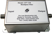
Semi-Adjacent Bandpass (any channel 5-890 MHz)
CF7 and CF7 HR Series - General Purpose Bandpass Filters
CF7-CH.#
Dim 4.5 "L x 2.5"H x 1.75 "W
CF7-CH.# HR
Dim 7.5 "L x 2.5"H x 1.75 "W
 Outdoor model
 Dim: 4.25"L x 3.25 "W x 2.55"H
Designed to pass desired TV channel, and typically roll off >25 dB ± 5-6 MHz (VHF HR series) from passband edges (details- see Specs). Available for CATV and ATSC systems. Available for 6 MHz HD applications as well as 8 MHz European standard. Applications: Pass preferred signal band for receive systems, or, suppress spurs at signal source for signal distribution systems.
CF7 sample graphs
CF7 HR sample graphs
- Available channels: CATV: T7 - T13, 2 - 135; TV-IF, and, UHF 14 - 51
- Special models for FM band, and, +700 MHz Safety and Commerial bands
- Passband Group Delay: < 50 nSec; Ripple: ± .5 dB; Return Loss: >16 dB
- Selectivity: semi-adjacent (details- see specs)
- Operating Bandwidth: 5 to 800 / 1000 MHz
- Custom passband: any frequency band ( from 4 to 12 MHz wide), within 4 to 800 MHz (see graphs)
- Various connector options (details- see custom info)
- Optional adjacent channel selectivity available for for chs: T7 to T13, IF, 2 to A14

Example CATV channel Graphs
CF7-chs T10, 3, 59 and 78, Specifications, Custom Info
UHF/Hyperband/LTE Cavity Bandpass 460 to 850 MHz
BP7-UHC High performance bandpass
UHF or CATV Hyperband, cavity-type, single channel bandpass with low loss and highly selective skirt. Low profile - fits into one rack space. Suitable for reception and low power (10 watt) transmitter applications. Standard bandpass is available with 4 cavities. Bandpass channel is user specified and can be factory re-channnalized.
- Available for 460 to 850 MHz: chs 14-69 UHF; chs 62-125 CATV, and LTE Block (A,B,C -700-750 MHz)
- Available with 3 to 6 cavities (4 cavities standard)
- Available with notch filters, or up to 6 cavities, for greater selectvity
- BP7-UHC can be re-channelized from 470-600, 570-720, or 720-850 MHz
- Passband Bandwidth: 4 to 8 MHz (e.g., for ATSC or PAL formats) *
- Passband Loss: <2.0 dB; Stopband (4 Cavity): >25 dB ± 8 MHz from bandedge
- Return Loss: > 16 dB
- Rejection From Passsband edge (2 dB insertion Loss):
3 Cavity 4 Cavity 5 Cavity 10 dB +/- 5 MHz +/- 4 MHz +/- 3 MHz 25 dB +/-9 MHz +/- 7 MHz +/- 6 MHz 50 dB +/-22 MHz +/-18 MHz +/-16 MHz - Reject Band: 5 MHz to 1 GHz
- RF Power Handling: 10 Watts max
- Connectors: "F" females (standard), 50 BNC/N optional
- * Special order for passband up to 18 MHz (3 cavity)
Narrow-Band Bandpass (Fixed & Tuneable)
NF7, NF7-HQ, and VF7 - Narrow Bandpass Filters
 NF7-Fc
 Dim 3.6"L x 2.5"H x 3.2"W
NF7-(Fc)
Passband: 1 to 2 MHz
- Fixed frequency filter. User specified passband
(Fc - 4.5 to 250 MHz) - Stopband rejection:> 25dB at ± 3 MHz from Fc
- NF7 is similar to VF7 (below) but not tunable. NF7 is trap enhanced for greater selectivity (i.e., >40dB rejection at ±12 MHz Fc)
Model NF7 is designed to pass a narrow, 1 MHz, frequency band while attenuating all other signals. All models are 75 ohms impedance with F-type connectors (optional 50 ohms with BNC or N).
 NF7-(Fc) HQ
 Dim 4.25"L x 4"H x 1.75"W
NF7-(Fc) HQ
Passband: 0.5 to 1 MHz (approx)
- HQ Helical resonator design
- Fixed frequency filter ( 75 ohms)
- Fc is available from 60 to 750 MHz
- Insertion at Fc: from 3 to 5 dB
- Return loss: 16 dB typical
- Can be trap enhanced for greater selectivity
- Selectivity ( 20 dB rejection points ):
VF7-(Fc)

Passband: 0.5 to 1 MHz, frequency tunable
- Factory pre-tuned to specified frequency (Fc)
- Passband insertion loss is <3 at Fc
- Stopband rejection: 15dB min at ± 3 MHz from Fc
- Tuning range is approx ±10 MHz.
- User adjustable via two screw trimmers
- Fc available from 60 to 600 MHz

Example Graphs
NF7-4.5, NF7-76 HQ, NF7-721.25 HQ, VF7-180
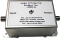
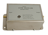
Adjacent Channel Wide-Bandpass (custom within 3 to 560 MHz)
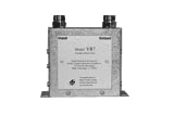
BP7-CEW
Bandpass filter network consists of adjacent channel lowpass and highpass joined together to form a wide bandpass. Custom ordered to pass several consecutive channels. Example: CE7-BP ch.50/56 - pass chs 50 to 56, rejects ch. 49 below, ch. 57 above, and all other channels.
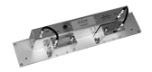
 BP7-CEW (50 dB)
Dim 3.5"H x 19"L x 6"D (or 5.25H)
- Adjacent channel selectivity
- User specified passband ( Fc1 to Fc2 ), for frequency band within 5 to 560 MHz (or chs T7 - 85)
- Passband loss: < 4 dB ( except band edges - Fc1 and Fc2 - depends on frequencies - see graph).
- Stopband: > 25 dB on adjacent channels (greater attenuation , e.g., > 50 dB - inquire )
- Operating Bandwidth is 5 to 750/1000 MHz
- Temperature stable (-10° to +40° C)
- Models also available with semi-adjacent selectivity

Example Graphs
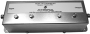
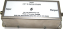
Wide Bandpass, Non-Adjacent Filter (within 3 to 860 MHz)
CF7W and CF7W HR
CF7W
Dim 4.5"L x 2.5"W x 2.5"H
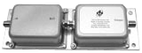
CF7W
Dim 3.5"W x 7"L x 2"H (or 4H)
CF7W, custom wide bandpass, combines sharp lowpass and highpass filters
together for desired passband., with 5% frequency transition from 3dB BW to 40dB stopband.
CF7W HR, custom wide UHF/LTE bandpass, combined Helical resonators to form highly selective bandpass. Available for TV or LTE 700 MHz bands from 400 to 900 MHz, with 6 to 50 MHz bandwidth, with <3.0% frequency transition from 3dB BW to 40dB stopband.
CF7W and CF7W HR standard connectors is 75 ohms F-female. Also available with 50 ohms impedance with BNC, N or SMA connectors.
CF7W-698/746 HR - Provides spurious suppression for a group of consecutive RF channel modulators.
- Available for standard CATV, VHF and UHF - click for table showing a variety of CF7W models
- Customized to pass desired segment of the TV spectrum ranging from 5 to 860 MHz (Fc1 to Fc2 )
- Passband loss: < 2 dB (except 3dB at cut-offs)
- Ripple: < 1dB (<.5 dB for noise filters applications)
- Stopband: > 40dB (custom levels from 20 to 60 dB)
- Selectivity: > 40dB roll off at frequencies 4% above and below cutoffs, Fc1 to Fc2 (see graph)
VHF, VHF-UHF and UHF Wide Bandpass Filters (54 to 700 MHz)
CF7W Wide Bandpass Filters for Off-the-Air TV System
UHF only bandpass: 470-600 MHz Pre-selector filters
CF7W-470-600
Dim 4.5"L x 2.0"W x 1.75"H
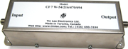
CF7W-470-600/617
Dim 7..5"L x 2 "W x 1.75 "H
CF7W-470/600 and CF7W-470/600/617 CF7W Multi-channel Bandpass VHF-HI to UHF bandpass: 174-700 MHz Pre-selector filter
CF7W-vhf-uhf-bandpass
Dim 4.5"H x 2.5 "L x 1.75W
CF7W-VHF-Hi-UHF VHF-Low (54-88 MHz), VHF-Hi (174-216 MHz) Pre-selector filters
CF7W-VHF-Low or Hi
Dim 4.5"H x 2.5 "L x 1.75W
CF7W-VHF (Low/Hi) CF7W-VHF-Hi UHF only bandpass: 470-700 MHz Pre-selector filter
CF7W-UHF
Dim 4.5"H x 2.5 "L x 1.75W
CF7W-UHF Double Bandpass Filter : VHF / UHF Pre-selector filter
Examples passbands
CF7W 174-216/470-806 is low loss pre-selector filter that passes VHF chs 7 thru 13 and UHF chs. 14-69.
CF7W 54-216 MHz/470-700 is low loss pre-selector filter that passes VHF 2 thru 13, UHF chs 14 thru 52.
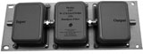 CF7W-174-216/470-806
Dim 3.5"H x 8 "L x 3.5W
 CF7W-54-216/470-700
Dim 3.5"H x 7.5 "L x 3.5W