Notch Filters for CATV / MATV / RF / FM Systems
Fixed and Tunable Models (0.8 to 1000 MHz)
Notch Trap Models
Off-Air Antenna Notches
- Off-air notches can have centre frequency 40 to 800 MHz
- Used to selectively attenuate desired frequencies to improve reception
- Bandwidth for VHF 40-250 MHz or VHF/UHF 40-250/470-800 MHz, or 40 to 800 MHz
- Models are available for 75 ohms (F, BNC) or 50 ohms (BNC, N)
- Indoor and outdoor enclosures available
RF Notch Filters (Custom): 0.8 to 1000 MHz, 75 or 50 ohms
- RF notch center frequency can be specified from 0.3 to 900 MHz
- Filter port impedance can be 75 ohms or 50 ohms (user-specified)
- Available with a variety of connector options: F, BNC, SMA, or N
- Details RF notch specifications - please refer to CATV and Off-Air TV/FM models
- Custom multiple notches for multi-frequency attenuation (seperate or contiguous) available
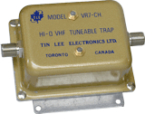
VR7-(Fo) HQ Series

VR7-(Fo) Tunable VHF/CATV Trap
Tunable VHF and CATV Trap
Frequency tunable - suppress one frequency (Fo) using two adjustable trimmers
- Six models covering: VHF low, VHF high, FM, CATV Mid1, CATV Mid2, CATV Super
- Rejection: > 40 dB at Fo
- Selectivity Examples:
- 3 dB BW: ± 1.5 MHz (Fo < 200 MHz)
- 3 dB BW: ± 2.5 MHz (Fo < 300 MHz)
- Bandwidth: 5-550 / 10-750 / 40-860 MHz
- Fo: Factory-preset; field tunable via two trimmers
- Rejection: Individual notches are approximately 8 dB
CR7-HT Series UHF Adjacent Friendly Notch and Bandstop

 PDF Data Sheet
The CR7-HT series notches and bandstops are designed for TV/RF signal interference applications in the UHF/RF band up to 1000 MHz. These filters have high frequency selectivity and are suitable for adjacent channel applications.
- Fo: from 400 to 900 MHz
- Rejection: 15 to 65 dB at Fo
- Selectivity Examples:
- 3 dB BW: ± 1.0-1.5 MHz (25 dB at Fo)
- 3 dB BW: ± 2.0-3.5 MHz (40 dB at Fo)
- Operating Bandwidth: 5 to 750/870/1000 MHz
- Passband Loss: 1 dB ± 0.5 dB
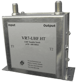
VR7-(UHF) HT
This series of notches is generally used to selectively attenuate one (or two) UHF signals. The VR7-470/600 HT, VR7-600/700 and VR7-700/870 HT models act on a preset UHF frequency range, whereas the VR7-(Fo) HT allows the user to specify an operating frequency (Fo) and notch depth for optimal selectivity.
- Fo: from 400 to 900 MHz (UHF / Hyperband)
- Rejection: >30 dB at Fo
- Selectivity Examples:
- 3 dB BW: ± 2.0-3.5 MHz (Fo = 470 to 600 MHz)
- 3 dB BW: ± 3.5-4.5 MHz (Fo = 600 to 800 MHz)
- Operating Bandwidth: 5 to 860 or 1000 MHz
- Passband loss: < 1dB ± .5 dB
Example Graphs:
CR7-(Fo) UHF HT
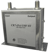
CR7-(Fo) UHF HT
UHF Single Notch
"Adjacent Friendly" UHF Single Notch - attenuate UHF frequency (Fo)
- Specify Fo: available from 400 to 800 MHz (UHF/Hyperband)
- Rejection: > 25 dB at Fo
- 3 dB BW: ± 1.0-1.5 MHz (Fo = 400 to 700 MHz)
- 3 dB BW: ± 1.5-2.5 MHz (Fo = 700 to 900 MHz)
- Operating Bandwidth: 5 to 800 or 1000 MHz
- Passband loss: 1 dB ± 0.5 dB
Example Graphs:
CR7D-(Fo) UHF HT
CR7D-(Fo) UHF HT
UHF Double Notch or 4-6 MHz bandstop
Fixed frequency UHF Double Notch - two >25 dB notches,or, one >50 dB notch, or, 4-6 MHz bandstop with high selectivity (Fo)
- Specify Fo: available from 400 to 800 MHz (UHF/Hyperband)
- Rejection: > 25 dB at Fo
- 3 dB BW: ± 1.0-1.5 MHz (Fo = 400 to 700 MHz)
- 3 dB BW: ± 1.5-2.5 MHz (Fo = 700 to 900 MHz)
- Operating Bandwidth: 5 to 800 or 1000 MHz
- Passband loss: 1 dB ± 0.5 dB
Example Graphs:
CR7-(Fo)-HQU and VR7-(Fo)-HQU:
CR7-(Fo)-HQU
UHF Frequency Notch
UHF Frequency Notch
Fixed frequency and tunable Single Notch - attenuate UHF frequency (Fo)
Fixed frequency model CR7-(Fo) HQU notch specifications:
- Fo: from 400 to 900 MHz (UHF/Hyperband)
- Rejection: >25 dB at Fo
- 3 dB BW: ± 6.0-8.0 MHz (Fo = 400 to 550 MHz)
- 3 dB BW: ± 8.0-12 MHz (Fo = 550 to 900 MHz)
- Operating Bandwidth: 5 to 860 or 1000 MHz
- Passband loss: < 1dB ± 0.5 dB
VR7-(Fo)-HQU
UHF Frequency Notch
Tunable frequency model VR7-(Fo) HQU notch specifications:
- Rejection: > 25 dB at Fo
- 3 dB Bandwidth: ± 6.0 - 12 MHz (Fo = 400 to 800 MHz)
- Bandwidth: 5 to 860 MHz
- Fo is factory preset and tunable via two trimmers (T1 and T2)
- Rejection: individual notches are approximately 7 to 15 dB
CR7-(Fo)-LQ (Fo - 5 to 1000 MHz)

CR7-(Fo)-LQ
Fixed Frequency Notch
This type of notch has less selectivity than an “HQ” notch and is used when high temperature stability and less selectivity is suitable. It is available for TV/FM/RF. Example graphs show double LQ notches for signal suppression for 450 MHz and 999 MHz RF system applications. Similar multiple LQ notches are use for UHF antenna bandstops and CATV semi-adjacent channel deletion filters.
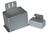
Outdoor Models
- Fo: from 5 to 1000 MHz
- Rejection: 20 to 60 dB at Fo
- Selectivity Examples:
- 3 dB BW: ± 2-3 MHz (25 dB at Fo, Fo 5-50 MHz)
- 3 dB BW: ± 3-4 MHz (25 dB at Fo, Fo 50-250 MHz)
- 3 dB BW: ± 4-6 MHz (25 dB at Fo, Fo 250-400 MHz)
- 3 dB BW: ± 6-7 MHz (25 dB at Fo, Fo 400-600 MHz)
- 3 dB BW: ± 7-8 MHz (25 dB at Fo, Fo 600-800 MHz)
- 3 dB BW: ± 8-10 MHz (25 dB at Fo, Fo 800-1000 MHz)
- Operating Bandwidth: 5 to 750/870/1000 MHz
- Passband Loss: 1 dB ± 0.5 dB
Example Graphs:
BR7-(F1, F2 ... Fn) HQ
Custom Multiple Frequency Notches
Multiple Frequency Notches in single enclosure
- Fo (< 350 MHz): up to seven notches
- Fo (< 650 MHz): up to five notches
- Rejection: >40 dB
- Bandwidth: varies with notch tuning
- Dimensions (in): 1.75 x 19 x 4 (rack or wall mount)
- Multiple notches can be consolidated at one centre frequency for a wider notch bandwidth of 1 to 4 MHz
- Example applications: multiple FM interference notches, Multiple channel negative traps.