MATV Headend System Design
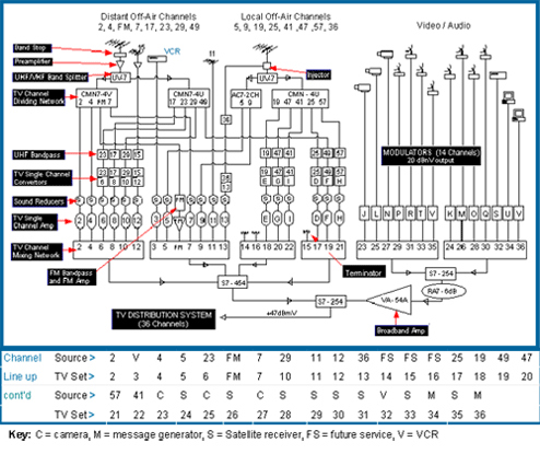
Fig.1: Diagram - Example 36 Channel MATV Headend System
This example headend serves to familiarize you with some of the headend products offered by TLE. Explanation of headend diagram provided below, or click on highlighted area.

Return to MATV Headend Products
This example headend serves to familiarize you with some of the headend products offered by TLE. Explanation of headend diagram follows.
Description: Headend Diagram ( fig.1 )
Headend System provides:
- 36 Adjacent TV channels, including: off-air broadcasts, satellite signals, VCRs, cameras, message generators, and FM band. System is expandable into super / hyper bands.
- High signal output level to deliver signals to 80 to 300 TV outlets
- Properly balanced and filtered signals, which prevents interference
Off-Air Antenna System:
Broadband antennas are used to receive broadcasts from two directions (local and distant sources). Two single channel antennas receive signals from other directions. They optimize signal reception (gain & directivity) of specific channels (ex: chs 11 & 15)
Bandstop, Injector, Bandpass, Sound Trap:
- Bandstop - CR7-5/9/FM, prevents strong local chs 5, 9 and FM band from entering and overloading the "distant" antenna preamplifier
- Injectors - AC7- ch.36, allows a newly received channel, e.g., 36, to be extracted from an existing antenna and routed to a channel converter
- UHF Bandpasses - CF7-UHF, passes only the desired UHF channel into respective channel converter (UHF channels are down converted)
- Sound Reducer Traps - CR7-ch.# S, adjusts the sound level of lower adjacent channel, to prevent sound interference on upper adjacent channel. Install at input of TA-62AGC single channel amplifiers (optional).
Preamplifier:
Broadband model, MA-25-77A, boosts weaker "distant antenna" signals, to compensate signal losses from antenna down lead and headend components (recommended signal level into headend components is +10 to +20 dBmV)
Channel Separation:
Signals from broadband antenna are divided into individual channels
in
two stages:
- UHF/VHF band splitter, UV7, divides the broadband signal into UHF & VHF bands - band splitters offer low insertion loss and high isolation ( passband loss .75 dB, and >50 dB isolation), and good return loss (>15 dB)
- TV Channel Dividing Networks: CMN7s divides the VHF & UHF bands into separate channels (2.5dB loss). Channels are subdivided into two non-adjacent groups (chs 2, 4, ..12, and chs 3, 5, FM ..13), and combined with a signal splitter. This ensures minimal channel interaction.
FM reception and signal processing:
Local and distant FM broadcast signals are received off "distant" broadband antenna.
- FM Bandpass. BP7-FM/6, blocks TV signals (including ch. 6) from FM system and blocks FM from entering TV system. FM filter passes signals from 90 to 108 MHz.
- FM Amplifier, TA-45-FM, provides 45dB gain for FM signal distribution.
- FM band is mixed with TV signal through a CMN7 FM port.
TV Channel Converters ( UHF to VHF ):
Channel converters, TC-Series, UHF channels are converted to lower frequency VHF and CATV mid-band channels. These channels suffer lower cabling and component losses.
Additional RF channel sources
(VCRs, satellite receivers, message generators, and cameras) :
VCR Ch. 3 Output: Ch.3 signal is amplified and filtered for adjacent channel operation (TA-62AGC provides filtering and +60 dBmV output).
TV Channel Modulators: TCAVM Series modulates audio/video signals into TV channel format for broadband signal distribution. Modulators outputs are combined and amplified (VA-54B - distribution amplifier ) to output level similar to single channel amplifiers (TA-62AGC) for delivery to distribution system.
- Stable Modulator Output level: +25dBmV (adjustable)
- Filtered for adjacent channel operation
- Crystal controlled frequency stability and accuracy
Single Channel Amplifiers:
TA-62AGC - Specially designed for off-air signal processing
- Stabilizes signal levels with automatic gain control (compensates input level fluctuations from -20dbmV to +40dBmV)
- Filters signals for adjacent ch. operation
- Amplifies the signal for distribution (+60 dBmV ±1dB)
TV Channel Mixing Networks:
CMN7, combines single channel outputs (from amplifiers & modulators) into one output (loss: 2.5 dB each channel). CMN7s also provides selective channel combining - rejects any spurious output with lower insertion loss than typical broadband splitter/tap combiners (e.g., CMN7 mixer loss - 2.5 dB vs. 8-way tap loss - 12 dB ).
Broadband Signal Distribution System
Headend provides +47 dBmV signal output. This is sufficient to deliver signals to all TV/FM outlets (80 to 300 outlets) connected to TV distribution system.